
Place OneU box upright on a flat surface, open the box and remove the top layer of packaging and accessories.
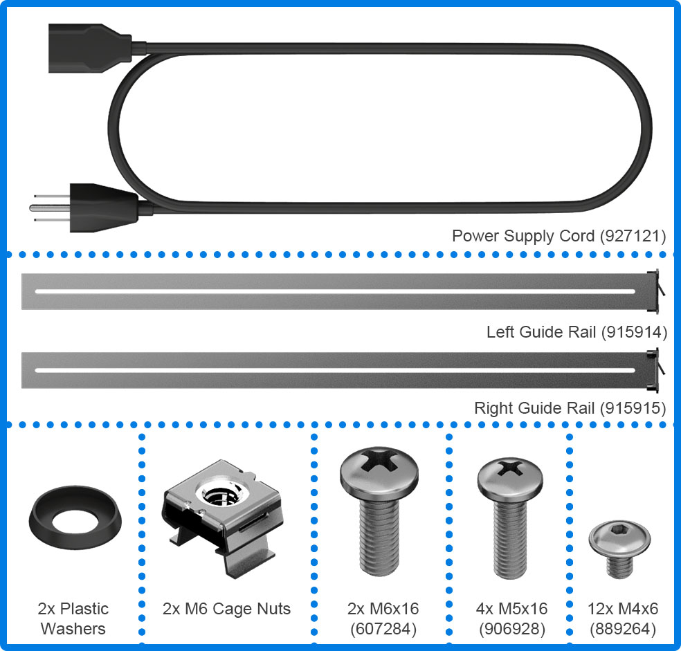
Check Box for the above contents.
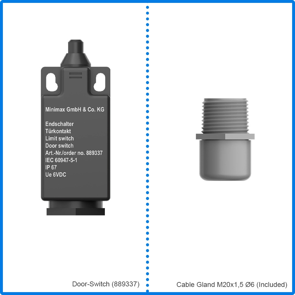
The door switch is ordered and shipped separately from the One U.
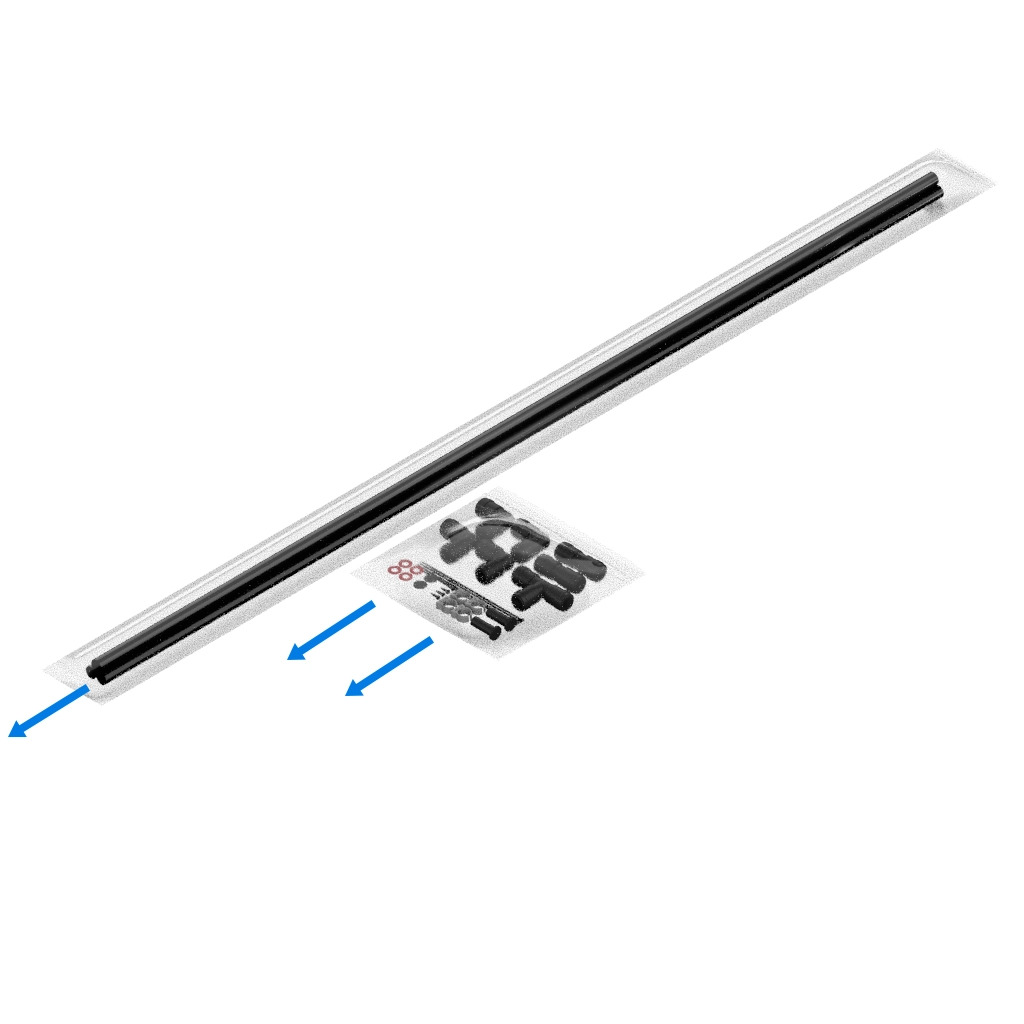
Open the air suction tubing package. The air suction tubing is ordered and shipped separately from the One U.
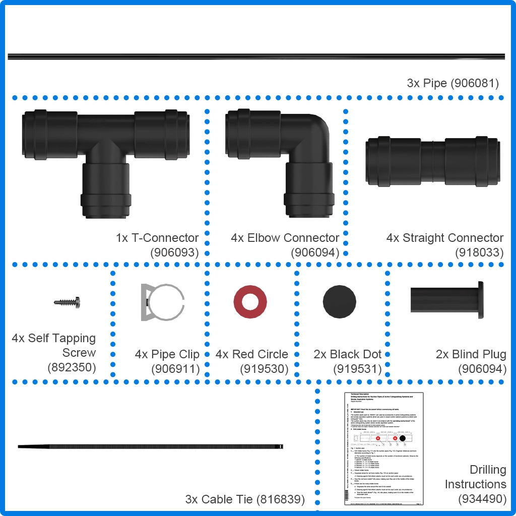
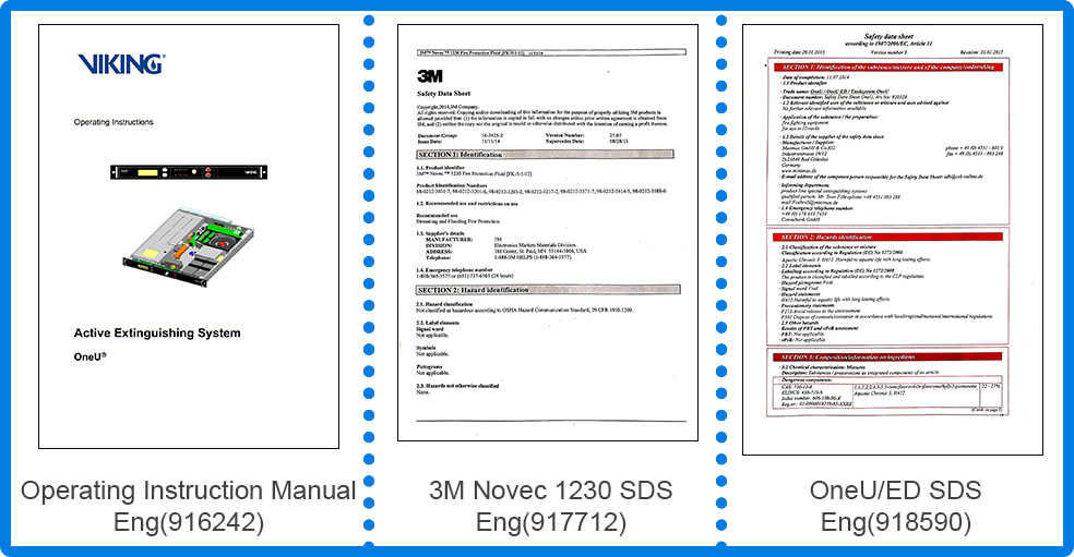
Check for the indicated items.
Remove the next layer of packaging and carefully remove the OneU and set it on a flat surface for initial setup.
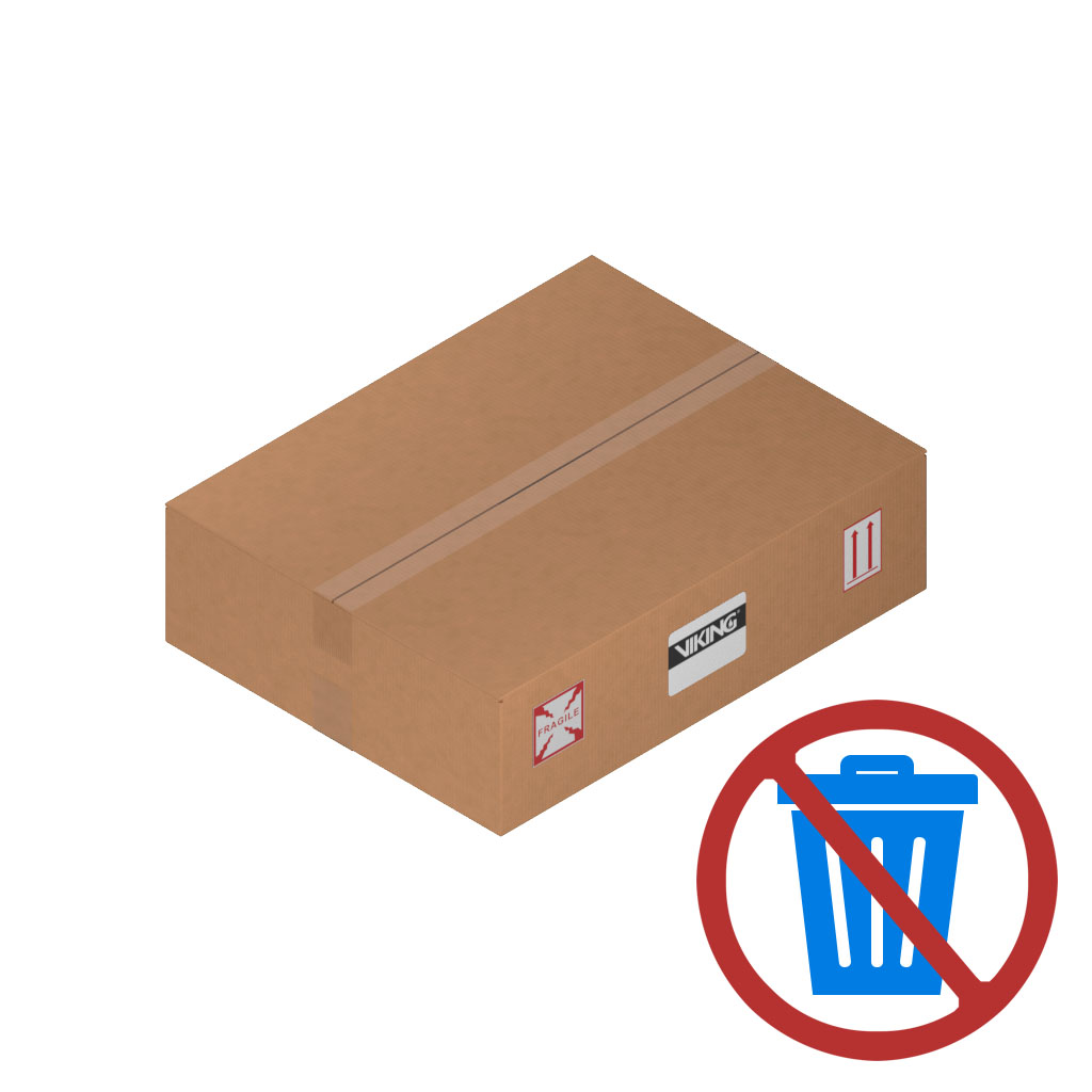
Do not throw out the packaging, if you need to return the unit for any reason it must be returned in the original shipping material.
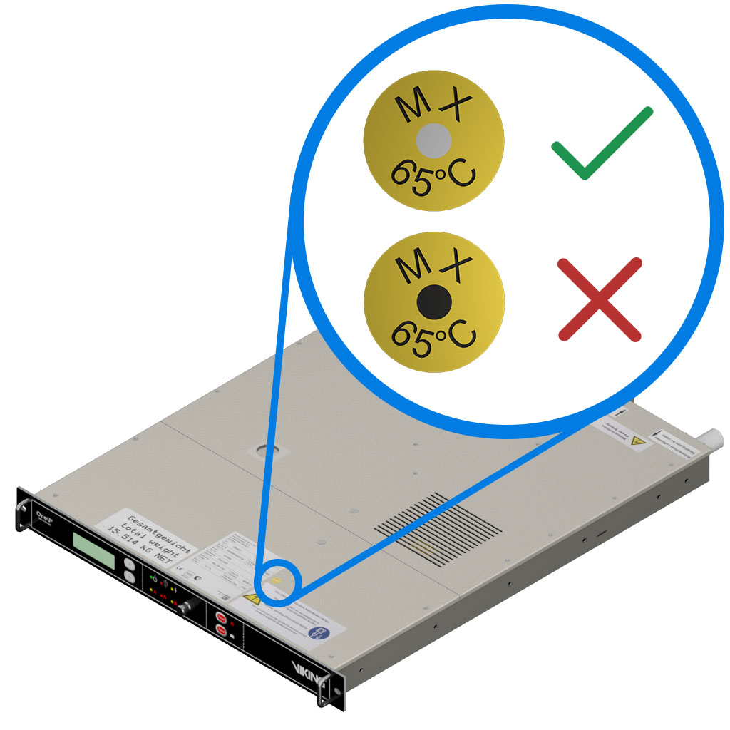
Inspect the temperature indicator to ensure it has a white center. If the center is black, contact your regions authorized service provider.
The switch should already being in the “Agent Disconnect” position, if it is not block the system from discharging during initial setup by moving the blocking switch to the “Agent Disconnect” position.
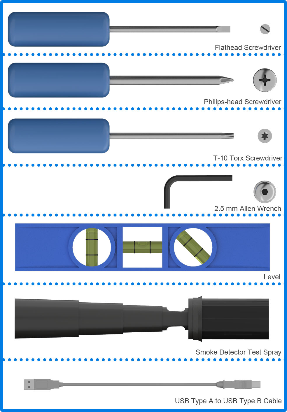
Remove the four screws on the front cover using a T10 Torx screwdriver, then slowly lift the front cover.
Disconnect the earthing cable.
Lift the panel off of the OneU.
Connect the batteries.
Replace the front cover.
Reconnect the earthing cable.
Close the front cover, then replace the four cover screws using a T10 Torx screwdriver.
Using the Torx screwdriver or similar tool, activate the system using the “Battery ON” button.
Check that the “Blocked” LED illuminates and the message “2 – Failure - Tank Triggering - Date/Time is displayed on the screen.
Gently lift the clear cover on the top of the OneU to access the dip switch.
Set switches 6 and 7 to the off position. This configures the door switch that will be installed later.
Move switch four to the ON position to change the language to English.
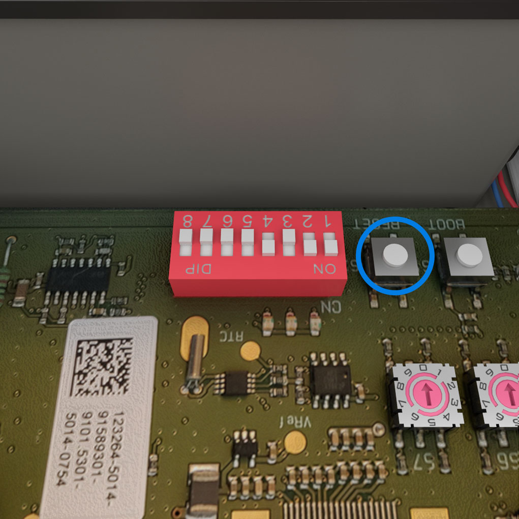
After changing the position of the switches press the RESET button directly next to the dip switch.
Using the Torx screwdriver or similar tool, deactivate the system using the “Battery OFF” button.
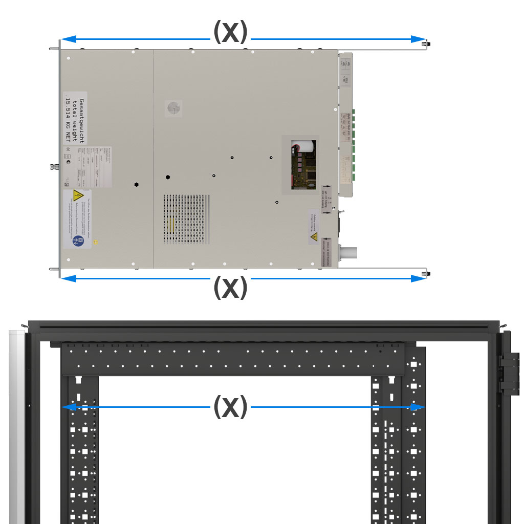
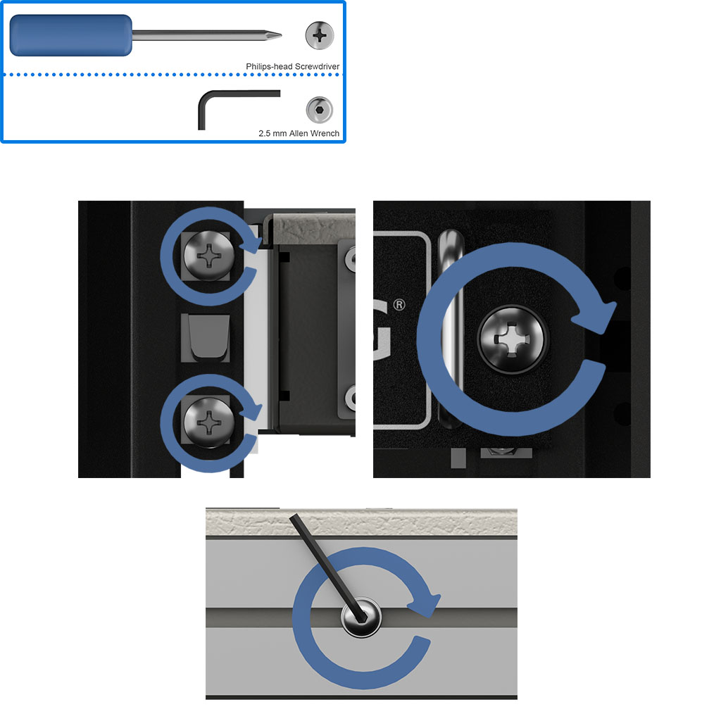
Measure the depth of your server rack and position the guide rails.
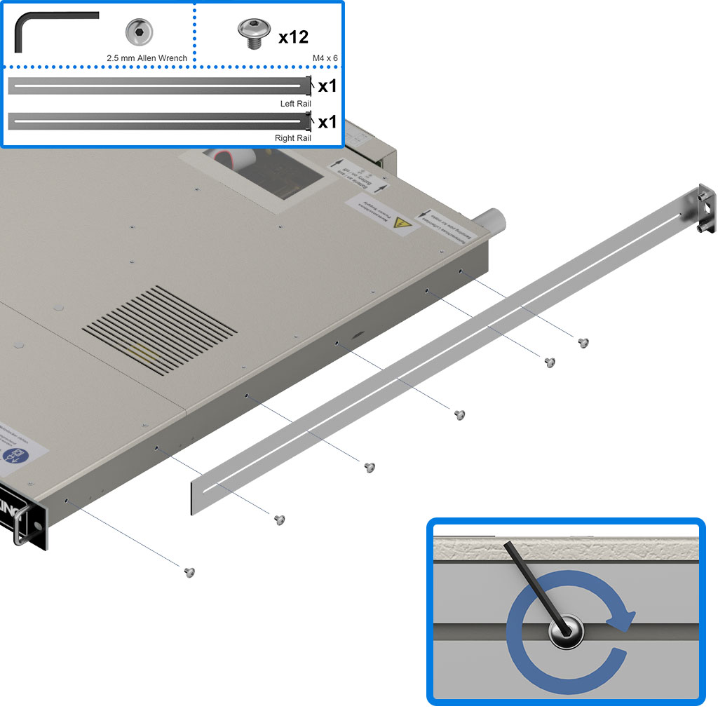
Using a 2.5mm Allen wrench, install the guide rail screws and tighten them.
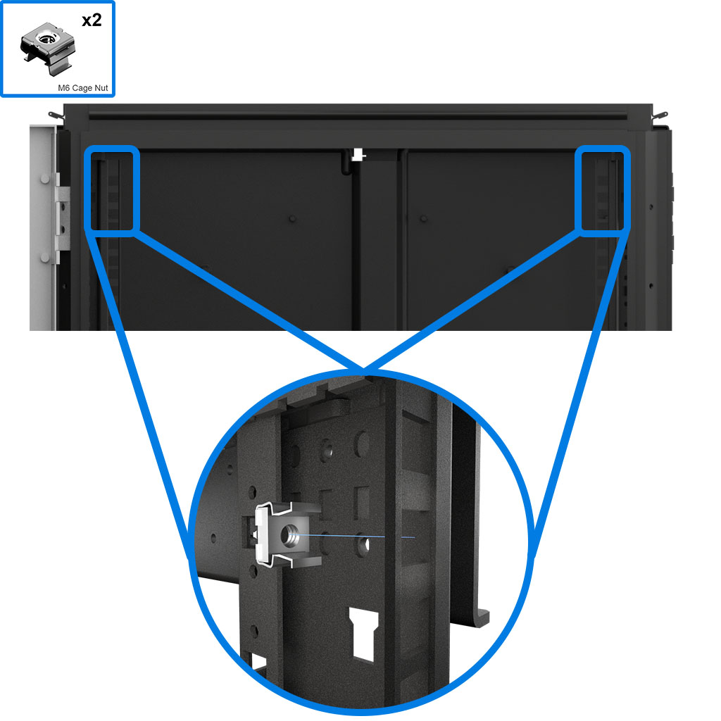
Insert the two Cage Nuts into the slots in the front of the server rack. The OneU must be mounted in the top 1/3rd of the server rack.
Insert the OneU into the server rack, make sure the guide rail noses fit into the slots in the rear of the server rack.
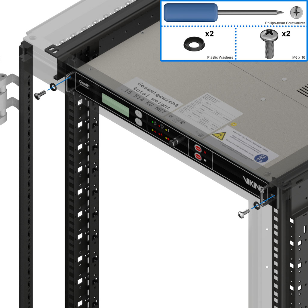
Fasten the system to the front of the server rack using the two M6 x 16 screws and two black plastic washers.
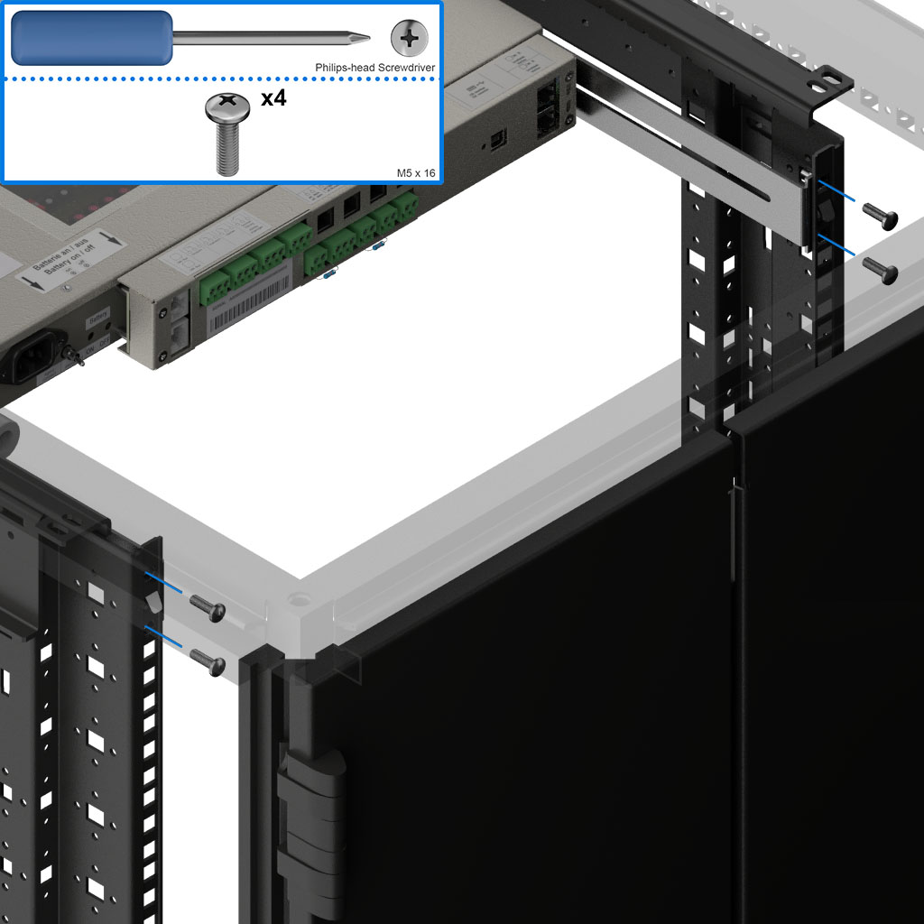
Fasten the rear of the system using the four M5 x 16 screws.
Confirm that all mounting screws are tightened before continuing.
Note: This guide will show the method to create a suction pipe system similar to the one described in “Section 5 – Mounting and installation” of the manual. Your particular server rack may require an alterative solution.
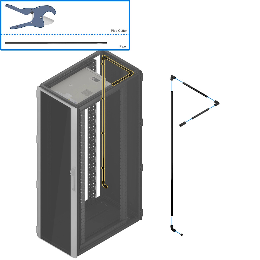
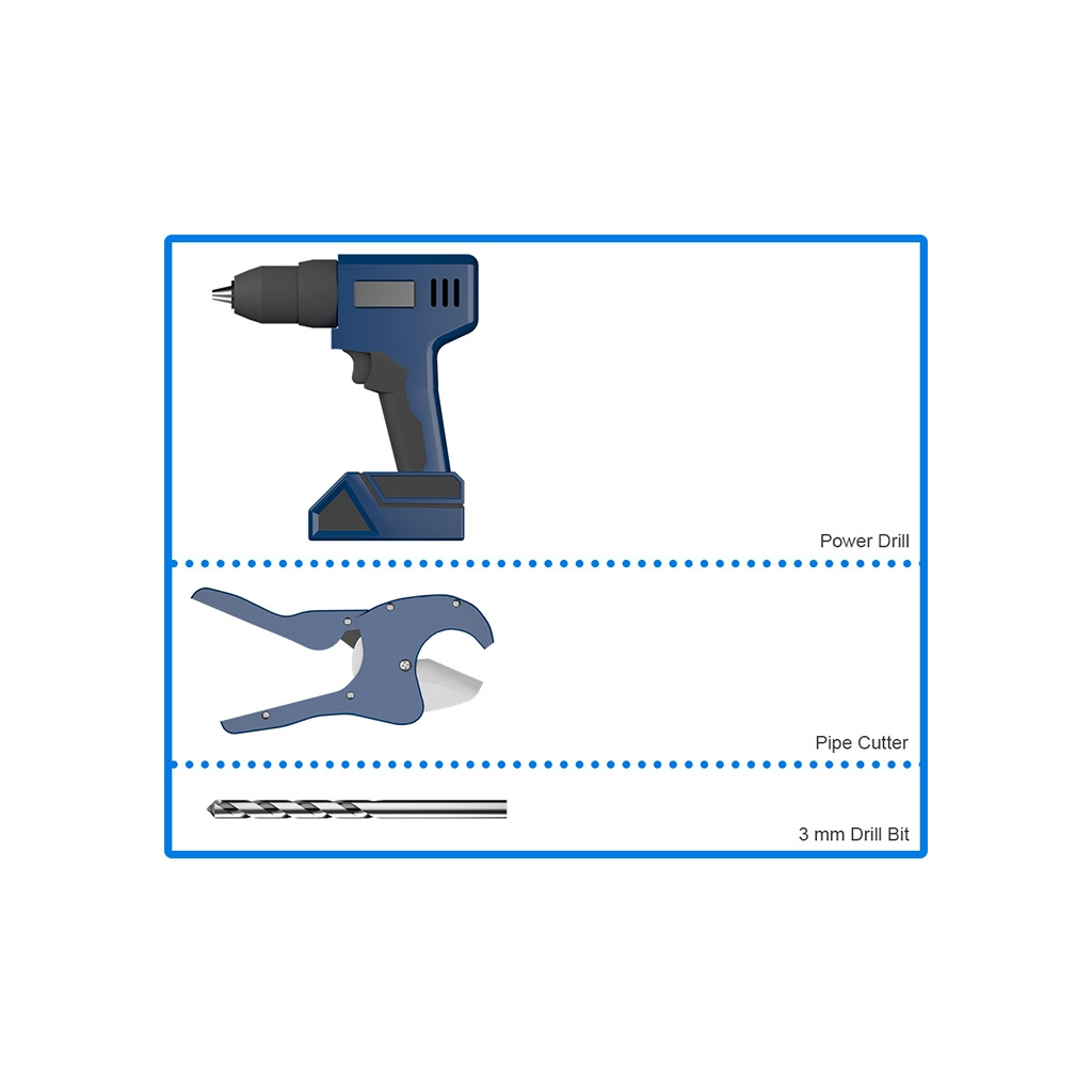
Plan where the suction tube network will be placed. While measuring the lengths for the suction piping segments, remember to take the pipe fittings into account. Cut the pipe according to your measurements.
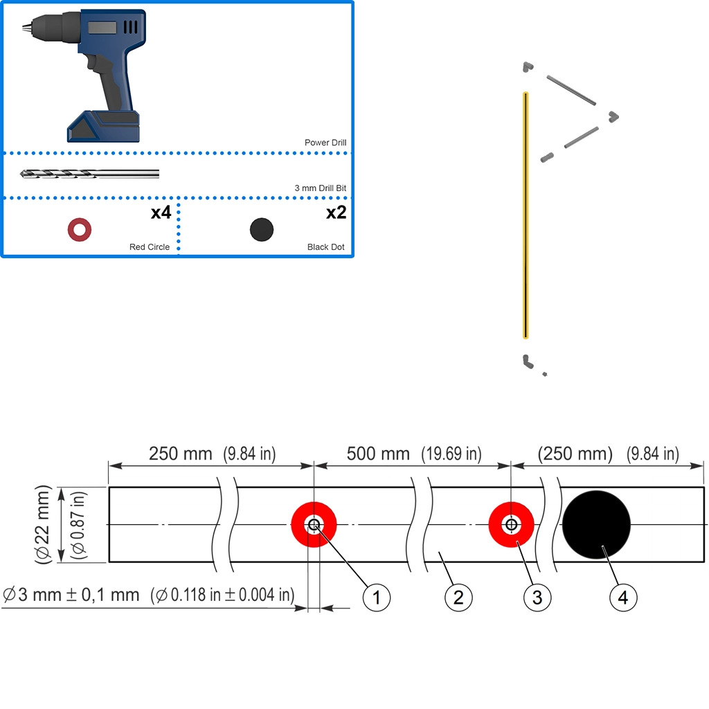
The vertical pipe segment will need sensing holes if they are not already in place. Using this diagram as a guide add four, 3mm holes (1) to the pipe segment (2)(if using more than one server cabinet consult the manual). Drill and deburr the holes then add the red circular sticker around each hole(3). If there are to many holes use the black stickers to seal them(4).
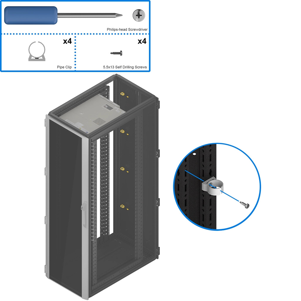
Mount the pipe clips in an appropriate area that will support the piping network
To connect the suction piping using the provided fittings:
Measure and mark the suction tube to the shown depth.
Insert the suction tube into the fitting up to your mark.
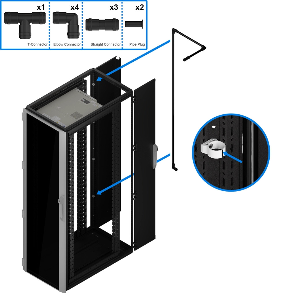
Assemble and install the suction piping network. Depending on how your piping network is configured, it may use all or only some of the provided connectors.
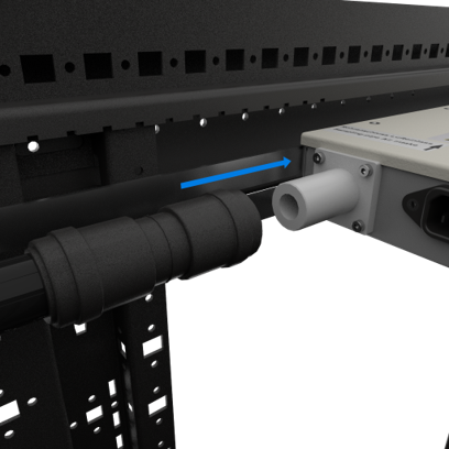
Attach the suction pipe assembly to the air intake on the back of the OneU
Remove the door switch cover.
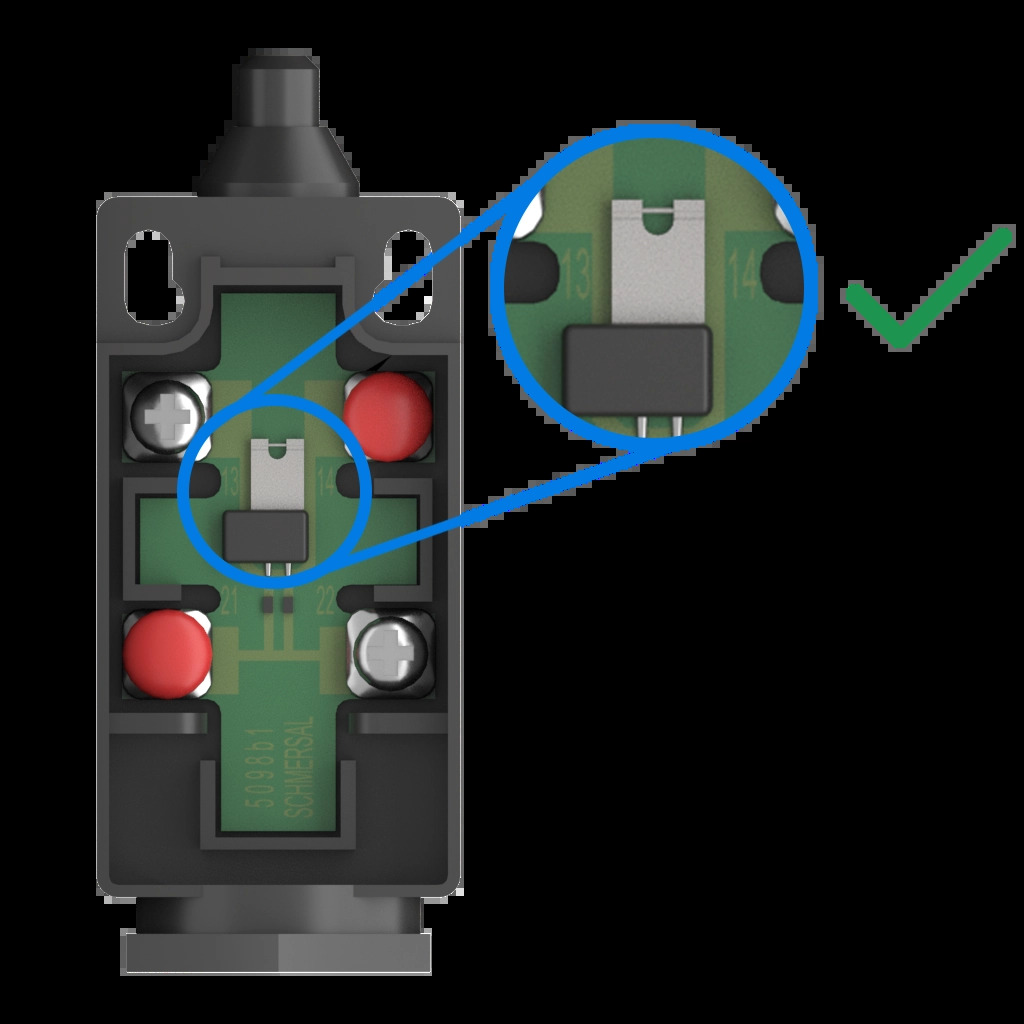
Make sure the grey jumper is in place.
Loosen the screws using a Philips-head screwdriver.
Insert the two leads as shown.
Tighten the screws using a Philips-head screwdriver.
Replace the cover of the door switch.
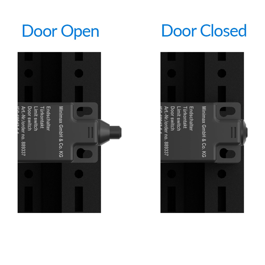
Position the switch so that the plunger will be fully depressed when the door is closed.
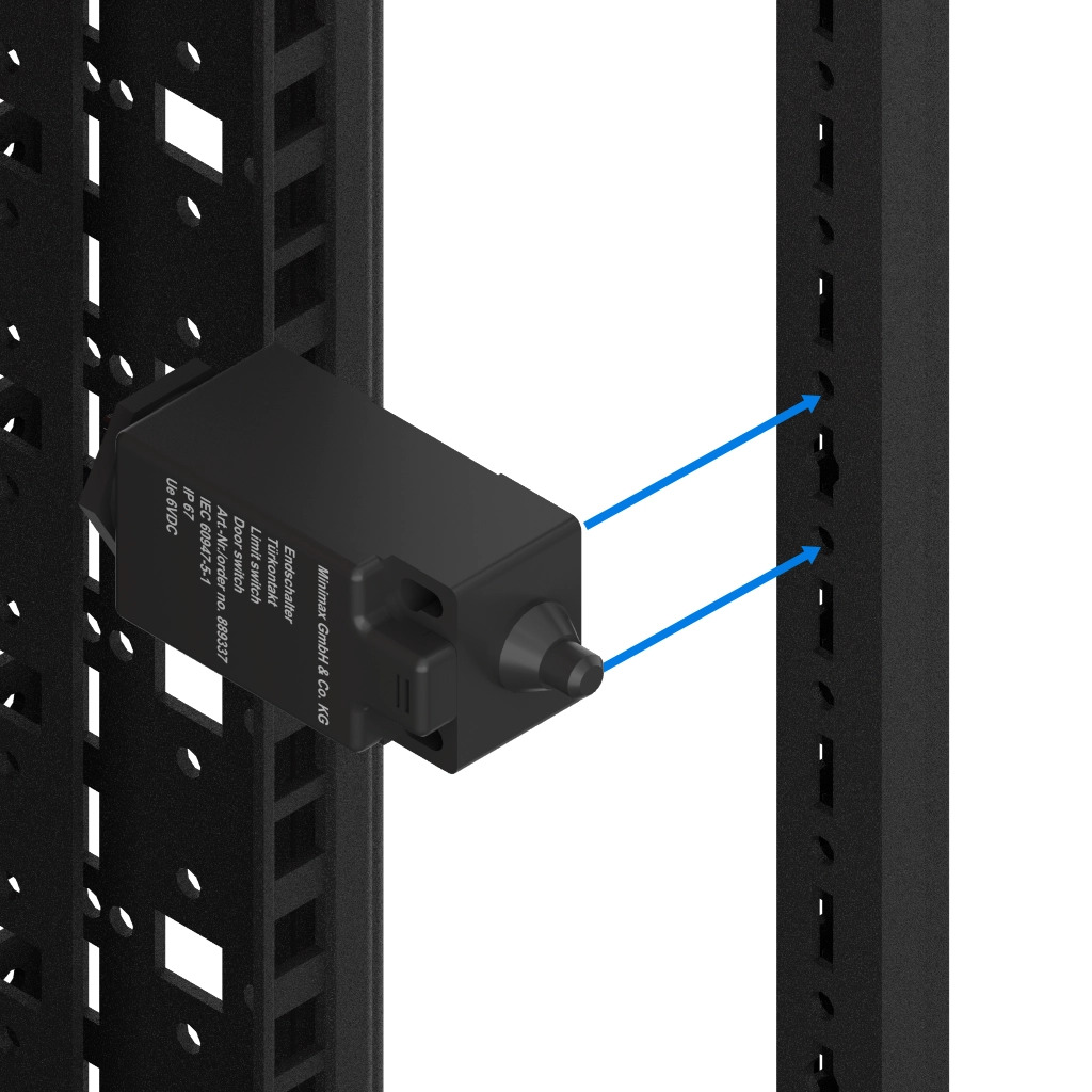
Using your preferred method, mount the door switch to the server rack, ensuring that the switch does not shift when depressed.
Remove the pre-installed resistor from connection 13 (as shown) to install the door switch leads.
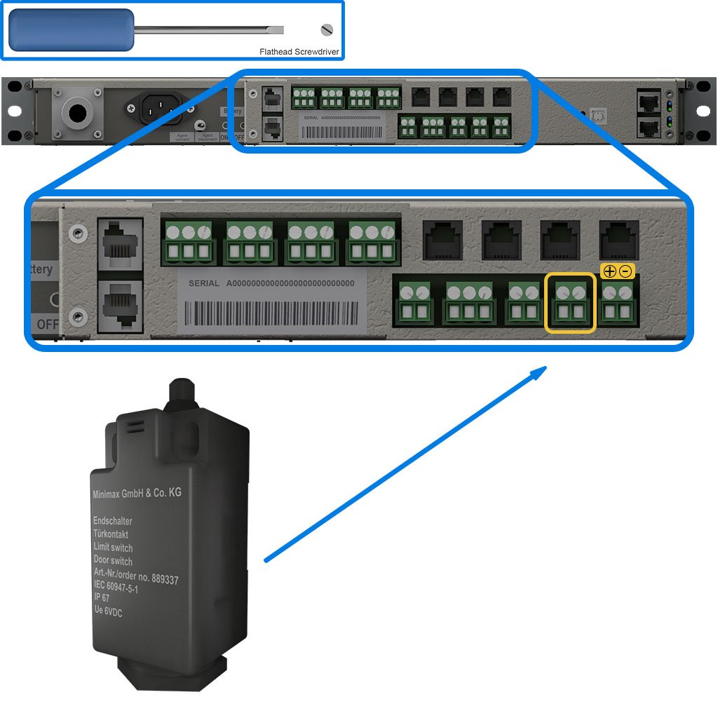
Connect the leads of the door switch to the highlighted connector. (Connection 13)
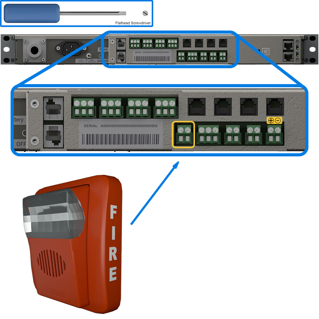
A horn-strobe device can be connected to the highlighted connection (Connection 10). The connector has a maximum allowable current of 24v 500mA. Consult the manufacture's installation instructions for your particular device.
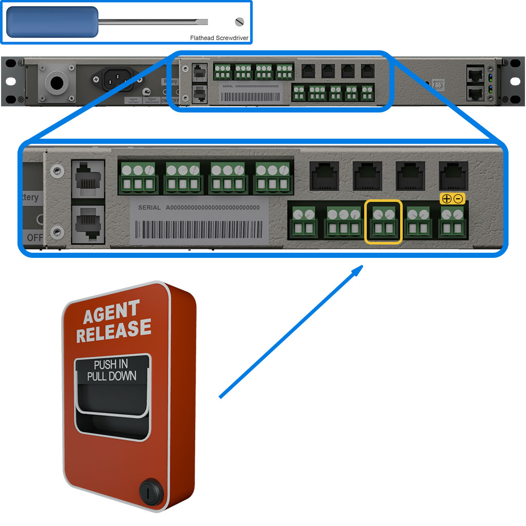
A manual release device can be connected to the highlighted connection (Connection 12). Consult the manufacture's installation instructions for your particular device.
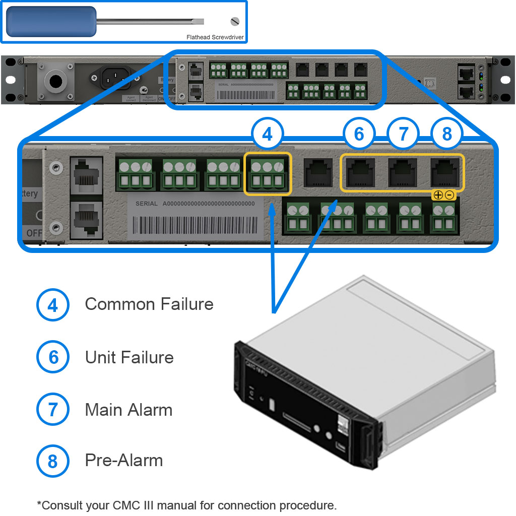
A CMC-III device can be connected to the highlighted connections. Consult the manufacture's installation instructions for setup information.
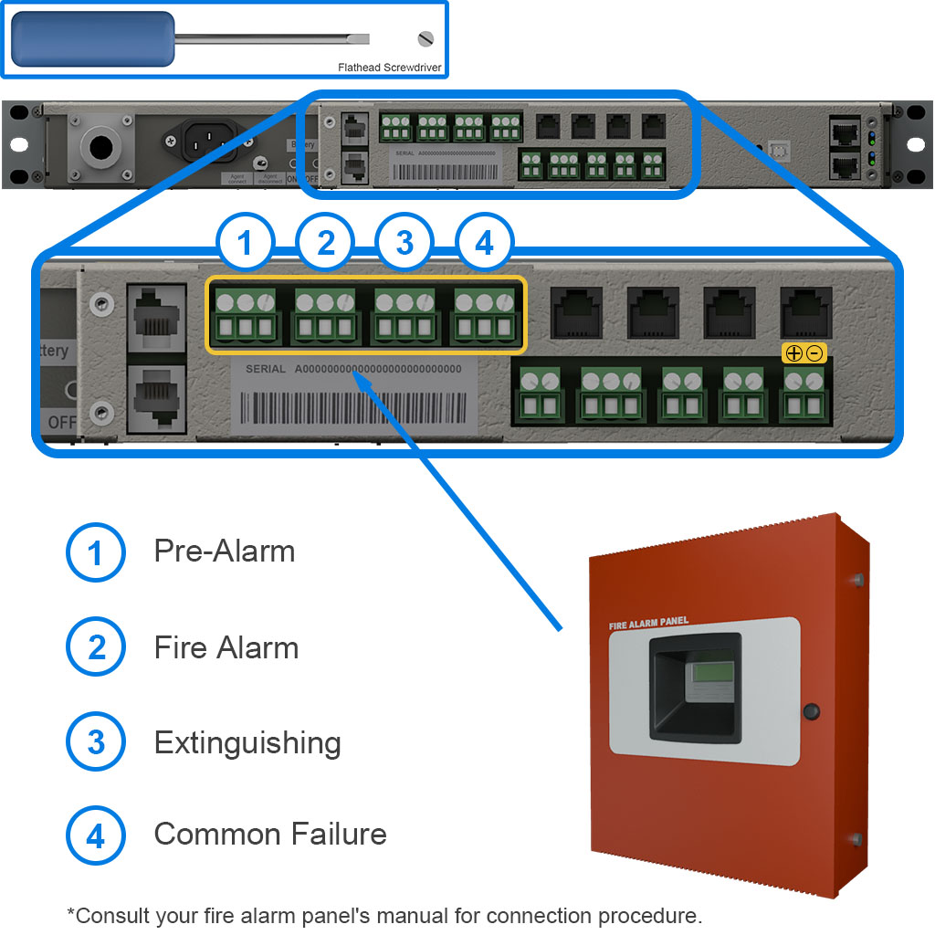
A fire alarm panel can be connected to the highlighted connections. Consult the manufacture's installation instructions for setup information.
Using the Torx screwdriver or similar tool, activate the system using the “Battery ON” button.
Connect the main power cord.
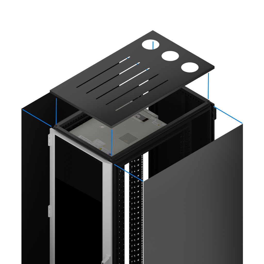
Attach any side, top, or rear panels to the frame of the server rack. Consult your server rack manual for additional instructions.
To calibrate the air flow, open the menu by pressing both the UP and DOWN arrows for 3 seconds.
Use the DOWN arrow to scroll until you see “Air Flow Calibration” then press the lower RESET button.
Press the DOWN arrow to see “Automatic Air Flow Calibration” then press the lower RESET button. Close the door and allow the unit to calibrate (this may take several minutes) and view the results on the following screen.
Then OneU is now calibrated. To get back to the main menu press the lower RESET button and then press the upper RESET button.
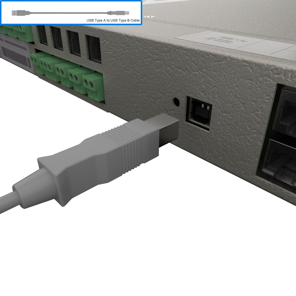
Configure software parameters using the maintenance software, you can get the software from the link provided below. Using an USB Type A to Type B cable, plug the USB-A end into your computer and the USB-B end into the OneU.
The configuration software can be downloaded from: https://www.vikinggroupinc.com/oneu
Open the maintenance software by double-clicking the application.
Read the data off of the OneU by pressing the “Read Data” button. Allow the data to load in.
In the left menu, click on “Customer Data”. Scroll down to “Battery Change” and change the value to “730”.
Next, in the left menu, click on the “Operation” button. Preform a lamp test by pressing the “Lamp Test” button. Click on the “Battery Change”, “Maintenance”, and “systemtime” buttons.
The OneU software is now configured, you can close the software by pressing the “X” button in the top right corner.
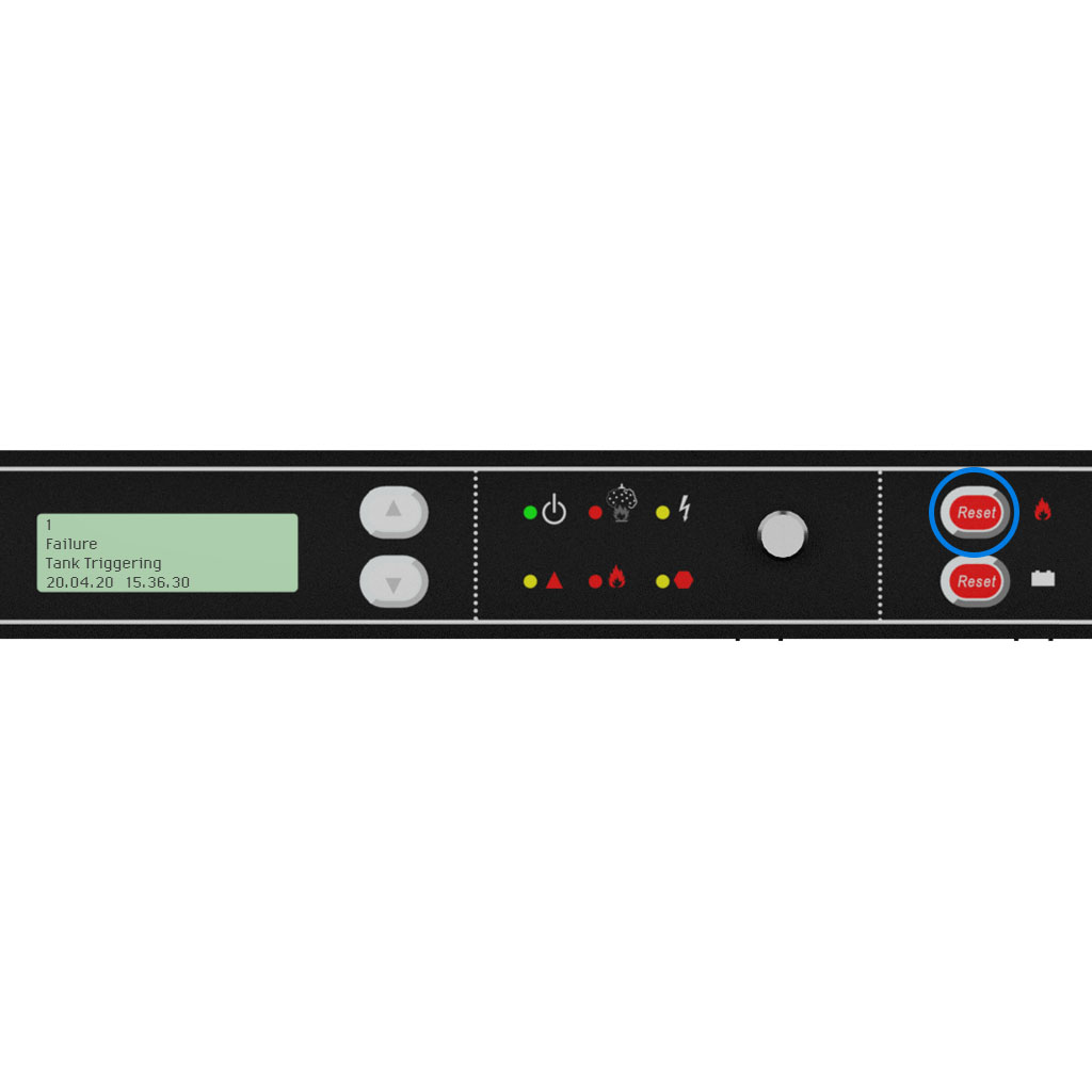
Check the screen and make sure the only error present is the “Failure Tank Triggering” error. Any other errors must be cleared by pressing the top “RESET” button. If you have issues consult the manual or call your authorized service provider.
Ensure the OneU is in “blocking mode” and preform a smoke test by spraying smoke near an air intake. Wait for the system to respond and illuminate the top middle “Extinguishing” light. If the system doesn’t respond call your authorized service provider.

2:00
Wait at least two minutes following the smoke test before continuing so that the concentration of smoke in the detector device dissipates.
Reset the alarms with the top “RESET” button.
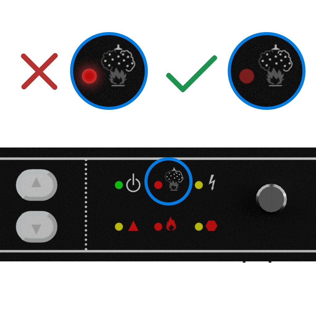
Check whether the top middle “Extinguishing System Triggered” LED is not lit. If the light is still lit, wait an additional five minutes for the smoke to dissipate and press the top “RESET” button again.
DO NOT continue if the light remains illuminated, as the unit could discharge.
Unblock the system from discharging by moving the blocking switch to the “Agent Connect” position.
Congratulations, your OneU is now in service!